Revit Snippet: Create Adaptive Curtain Wall with Multiple Attractors
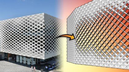
Do you know you can create this very dynamic façade using just Revit and a bit of Dynamo? Let’s walk through some easy steps to create this parametric curtain panel system in your Revit model today!
If you are short on time, the completed Dynamo script, panel family and Revit model can be download from here:
We will make use of 2 powerful Revit techniques: adaptive curtain panels and Dynamo. If you are new to Dynamo, don’t worry. This tutorial will give you an overview of what the script will do, and you can then just download it at the end to run it immediately in your Revit model.
On the other hand, adaptive components is a good training topic on its own. The best way to get familiar with it is actually use it. You can do that following this tutorial, and also a few other ones we will list at the end of this lesson. They all make good use of adaptive components to take our Revit modelling work to a whole new level. With adaptive curtain panels and its brother, adaptive components, you can truly apply some fairly complex computational design workflow right in your Revit model. Then, everything generated will be in place, ready for your drawings and design documentation.
Ready for that? Let’s drive right into creating this attractive architectural facade!
1- CREATE THE ADAPTIVE CURTAIN PANEL FAMILY
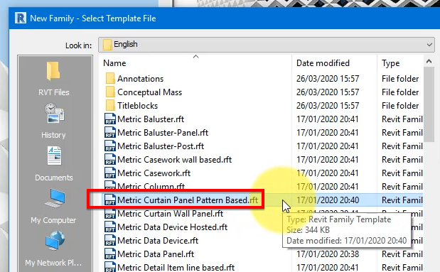
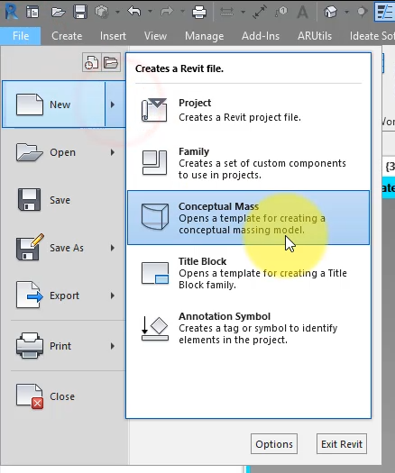
Go to File > New > Family and select the template called “Curtain Panel Pattern Based”.
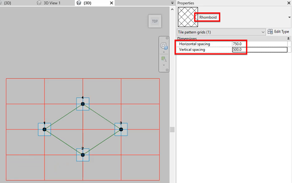
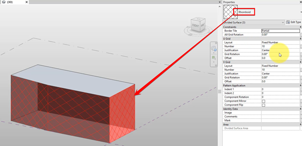
Under Properties of the family, change it pattern type to Rhomboid. Also here, set the values for Vertical and Horizontal spacing to roughly how much you expect each of your panels to be.
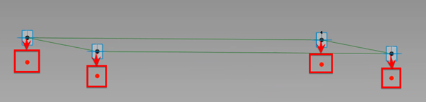
Next, create 4 new reference points hosted directly on top of the 4 existing adaptive/corner points which came with the family template.
Select these 4 new points and you will see a property called Offset.
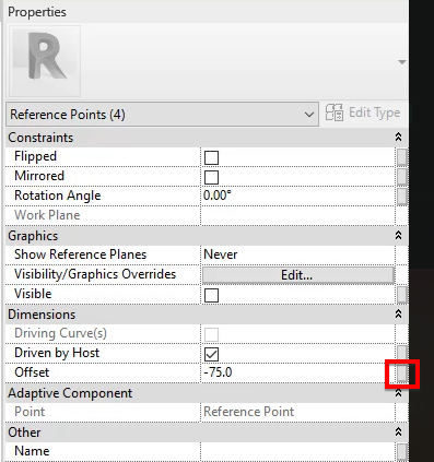
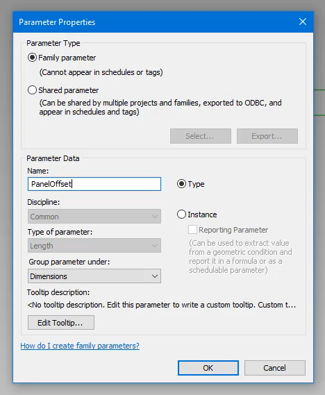
Click the box at the end of its line to lock it into a new parameter such as PanelOffset. Make sure it’s a Type parameter and not Instance.
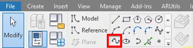
You can then select each pair of opposite points and use the “Spline through points” command to connect them, making 2 new lines like below.
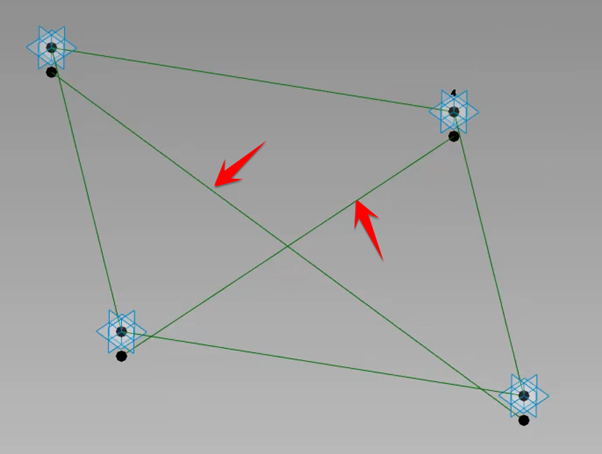
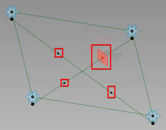
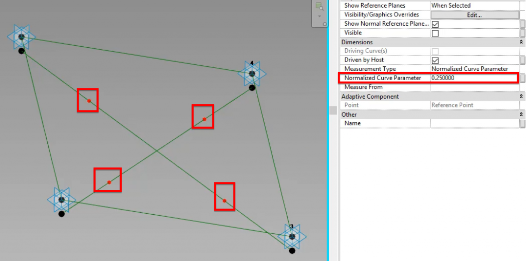
Moving on, let’s create 4 new points hosted on these lines at roughly the locations below.
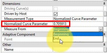
After placement of these points, select one of them and check back under Properties. You will see a new parameter called “Normalized curve parameter”. We need its value to be below 0.5 so if it isn’t, change the “Measure From” parameter right below it to a different value. For example, we changed it in the image below from Beginning to End.
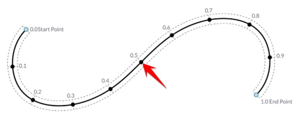
The purpose of this is to make sure each new point stays on its side of the line it’s hosted on. As you can see in the illustration below on curve parameterization, a point at parameter 0.5 will be exactly on top of its host line’s midpoint. Here, we want to have 2 points on each line, each staying on its side, so a parameter of less than 0.5 is required.
Repeat this check for the other 3 new points, then select all 4 of them. You can then give them the same value of 0.25 for “Normalize curve parameter”.
Next step, click the square button next to this new value and assign a new parameter to it. Use whatever name you’re comfortable with, such as my unimaginative “Param1”. The more important thing here is making sure this is an Instance parameter. The reason we don’t want this to be a Type parameter is because each of hundreds, if not thousands, of panels we will create from this family may need to have a different value for Normalized Curve Parameter. By making this an instance parameter, we can freely give each panel an individual value without having to make a new type each time we do that.
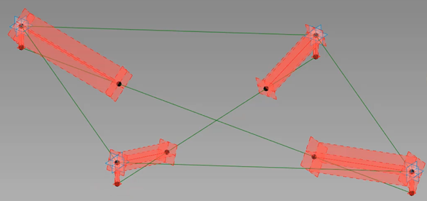
Moving on, let’s make sure of lots of points we’ve already created. Simply select them in pairs and use the same “Spline through points” tool from before to create 8 new lines below:
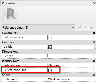
In case you haven’t noticed, they are reference lines. Those red/green planes around them is the giveaway. Make sure you tick the “Is Reference” box under their Properties to make this happen.
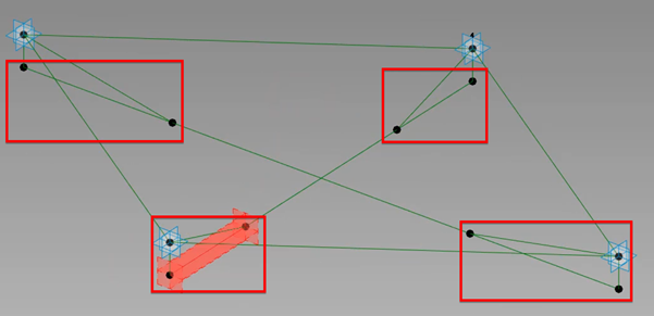
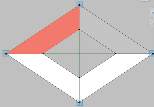
Using the same method, create 4 more reference lines to complete 4 triangles at our curtain panel’s corner points.
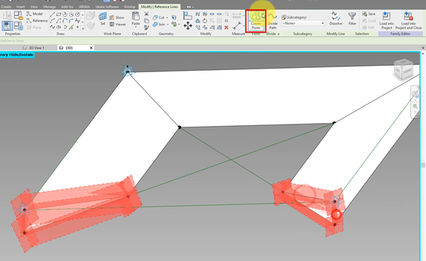
It’s now time to create some actual 3D geometry! Simple select each pair of triangles and launch the Create Form command from the ribbon.
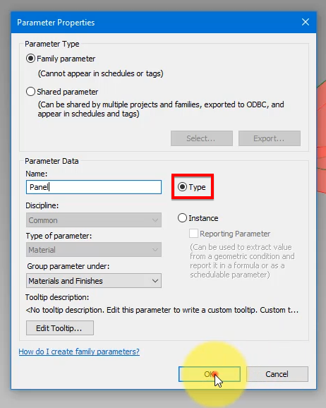
Next, select all 4 form items, check their Properties, and create a new parameter here to control their material later in the project. We will want to change it without having to return to this curtain panel family every time.
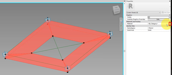
This one should be a Type parameter, because we will want all panels of this type to share the same material.
Next, we need to enable this curtain panel family to allow geometry manipulation on it later in the project. This property is quite hidden away. To see it, click the Family Categories button, and tick the box for “Cut with voids when loaded”.
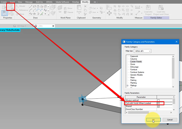
What this does is allow cutting certain panels later on if their geometry need to be slightly different from that of all their peers. Use this with caution because while it offers great flexibility, it makes it harder to ensure all panels of the same type share the same geometry.
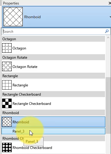
We now have a family ready for testing! Let’s save our curtain panel as “Panel_3”, and then create a mass family now to test it.
2-CREATE THE MASS FAMILY
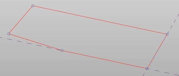
Here, it’s easy to start from the Line tool…

… And draw a closed boundary loop like below on the default workplane/level plane.
With that in place, select the boundary loop and run Create Form. You can then give the mass the desired height.
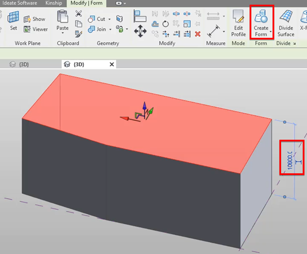
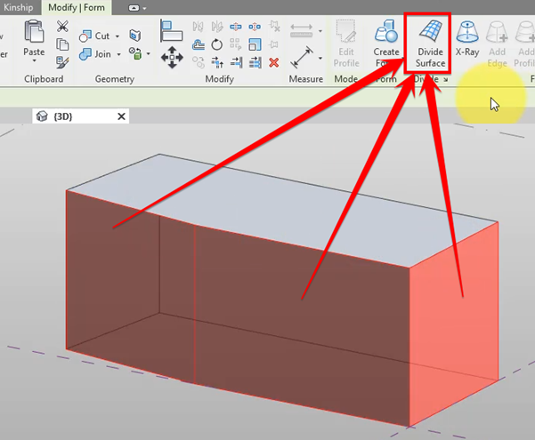
After this, select the front 3 mass faces. You may need to press Tab a few times to get to the right geometry element. Once that’s done, click Divide Surface.
You will see that by default, Revit applies a rectangular pattern to new divided surfaces. We don’t want that, so go to Properties of these surfaces and change the active pattern to Rhomboid.
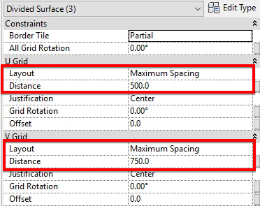
You can then change their Layout rules and distances as required. I went for Maximum Spacing here to reduce the number of partial panels during testing, but in a real life scenario, you’ll probably want to go for “Fix Distance”. While more precise, the latter may require you to edit your mass’ dimensions slightly to have the highest possible number of whole, uncut panels.
Here’s the exciting part! Load the curtain panel family created earlier into this mass family, then select your divided surfaces again and change their pattern type to the loaded family.
3-APPLY THE CURTAIN PANEL TO OUR MASS
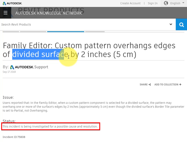
That will copy and array the curtain panel across all selected divided surfaces. You may already like the result at this point, which will be great. However, there are panels protruding beyond your surfaces’ boundaries.
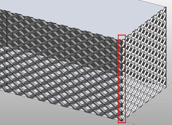
This is actually a known bug of Revit which has unfortunately remained with us for years. Just do a quick Google search and you will see even Autodesk hasn’t come up with a fix or solution!
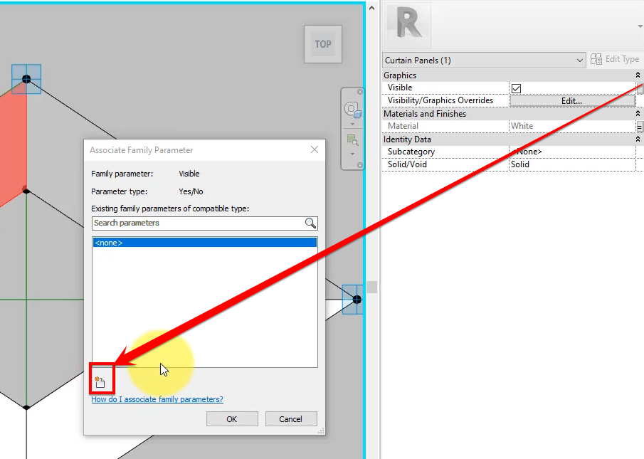
Well, don’t worry. We’ll use a few tricks to clean up these edges. First, go back to the curtain panel family and select one of the 4 form elements we created here.
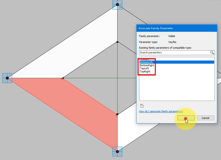
Under its Properties, click the box at the end of the line for Visible and create a new parameter to control this attribute.
This time, we need an Instance parameter of the Yes/No type and a name corresponding to the position of what we selected earlier. For example, name if TopLeft if you selected the same form object like we did.
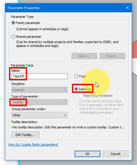
Repeat this 3 more times to create the same parameter for the other 3 form elements. The only thing different for each parameter is their name.
The next step is load the family back into our mass:
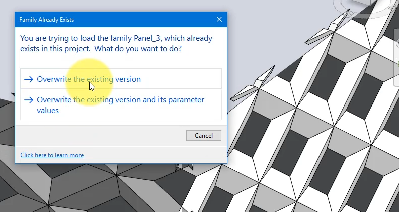
By doing this, we’ve made it possible to select any curtain panel on the mass and turn off some sections of it using tick boxes under its properties and clear the overhanging element.
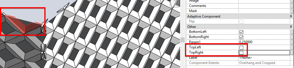
Of course, you don’t need to do this for each panel one by one. That would be very boring! Simply select those that need the same combination of tick boxes and change these for all of them in one go.
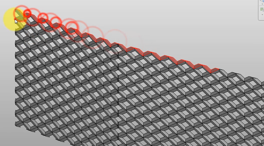
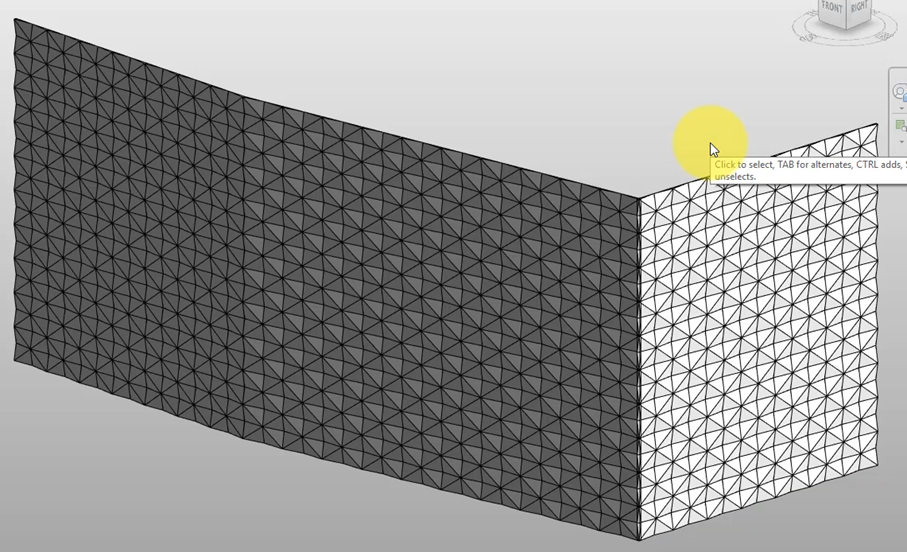
Before you know it, the whole thing will be done and look much cleaner, just like below. We need to tweak panels where our 2 surfaces on the right join at a right angle, but don’t worry, that will come a bit later.
To move on, select all curtain panels here, and change their Param1 parameter to make them close. We can’t use 0.5 here because that will create clashing geometry within each panel, so go for something close to 0.5, such as 0.495.
4-CREATE REVIT SHAPES AS ATTRACTORS
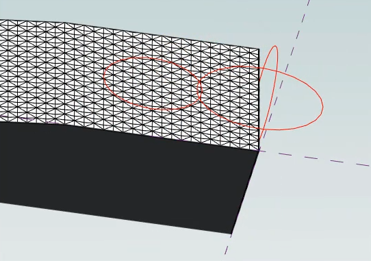
It’s time now to draw a few shapes which will act as our attractors. Our curtain panels will vary their opening sizes according to their proximity to these shapes. You can draw any shapes here such as rectangles, circles, or even just lines. For dramatic effect, we’re going for 3 ellipses as showed below. Make sure to set your workplane correctly before drawing each one to allow them to stay vertical.
5-GET THE DYNAMO SCRIPT READY
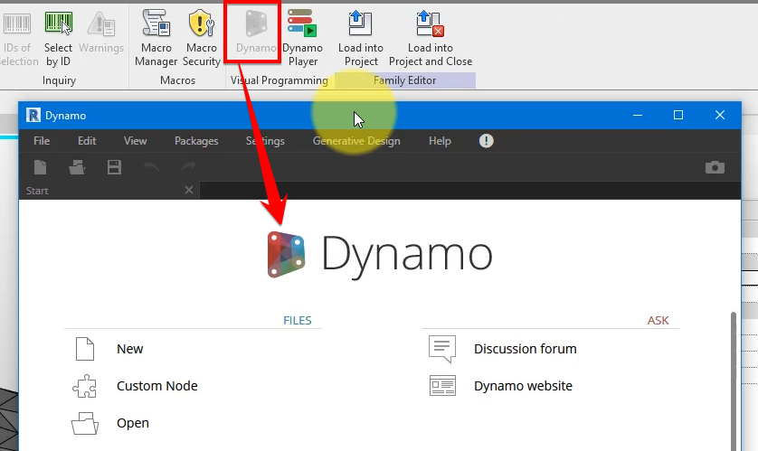
Next, we need to vary these panels’ opening sizes. It would take ages to do this manually for individual panels, so let’s use Dynamo! Simply launch Dynamo from your Manage tab to begin.
You can now follow the video tutorial at the top of this post to create the Dynamo script. The number of steps required in Dynamo just better suits this video format. You can also download this Dynamo script file directly here to save yourself some time.
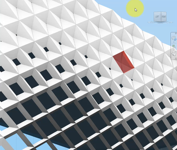
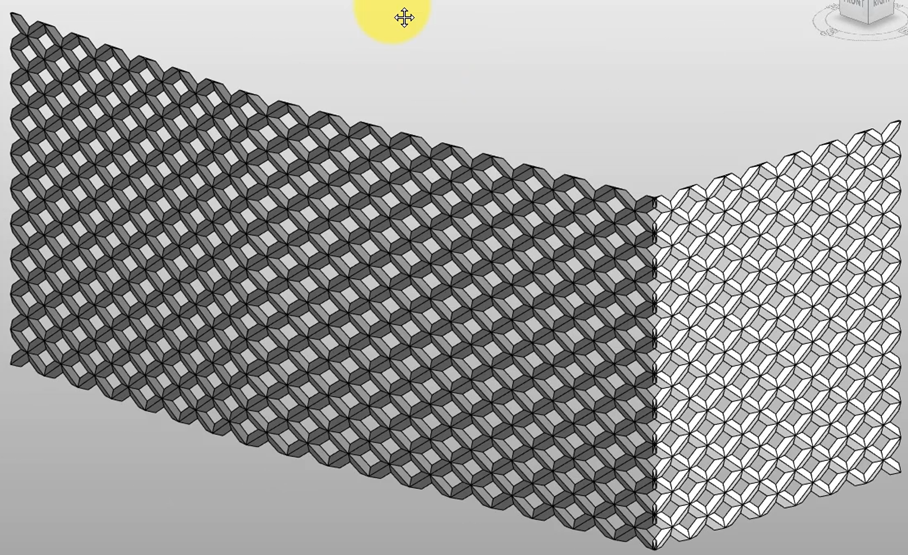
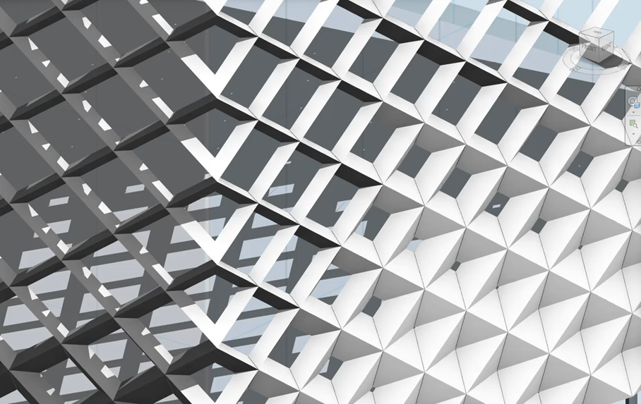
Once that’s done, run the script and your façade system should turn out like this:
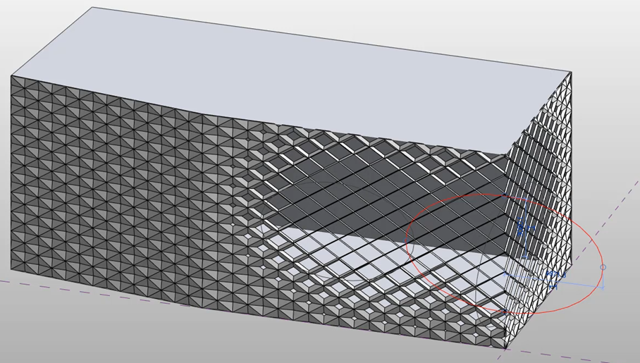
Nice! There’s a final problem though. Curtain panels along the edge where 2 walls meet are still slightly clashing with one another:
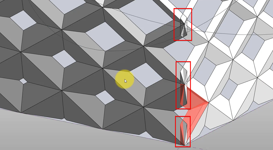
Don’t worry, we will fix them right now.
6-COMPLETE THE CURTAIN SYSTEM IN YOUR PROJECT
Let’s load this mass family into a new project model and then place it on a level or workplane.
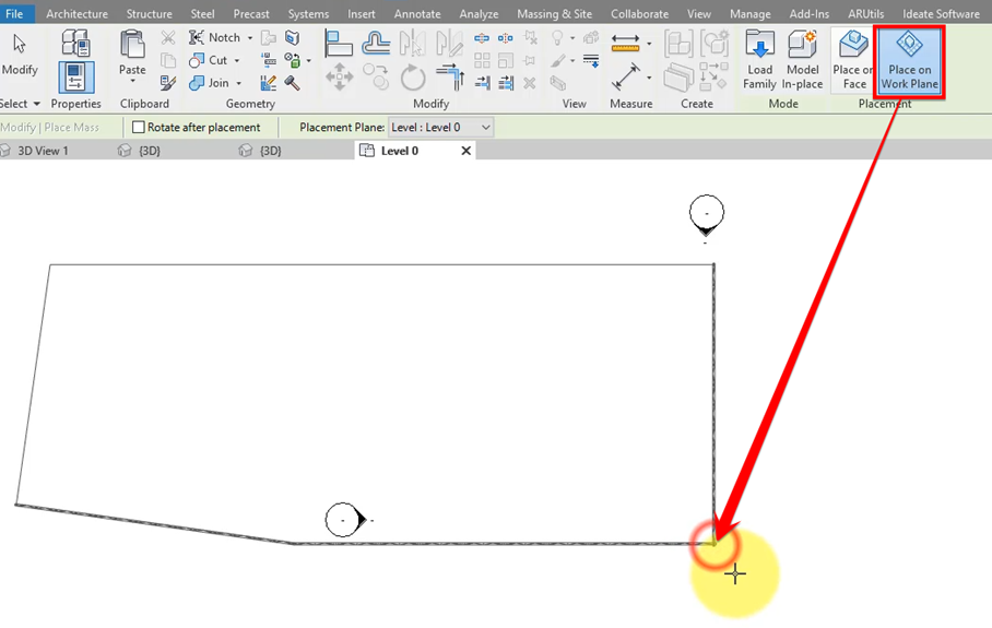
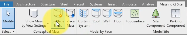
With the same workplane or level still active, choose to create an in-place mass.
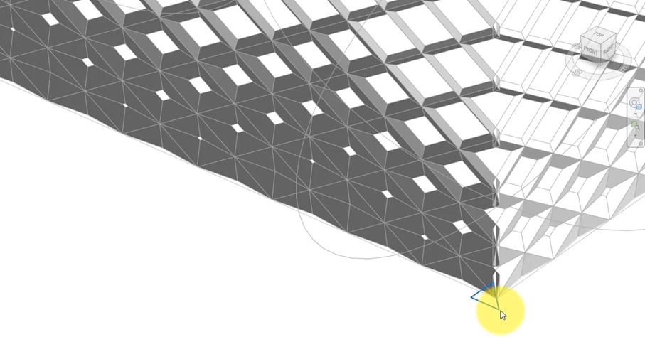
Then right below the corner where you have clashing curtain panel, draw a triangle similar to this one:
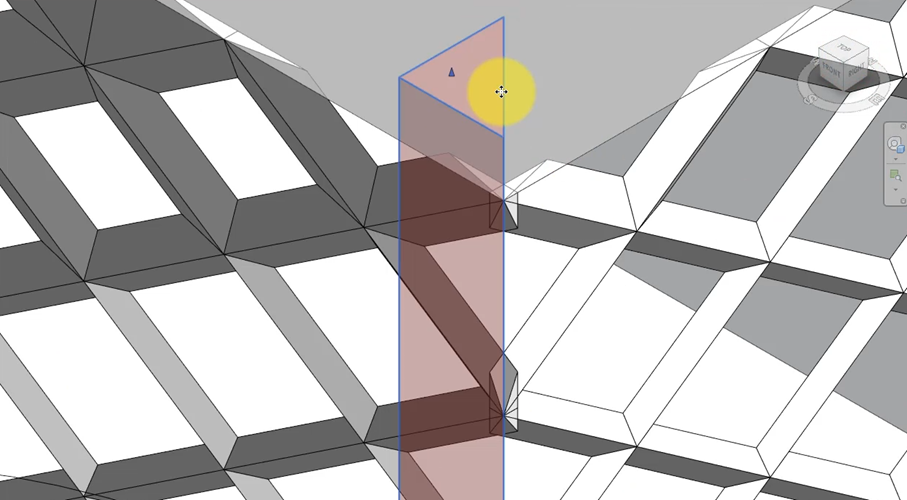
You can then click Create Form on the ribbon to extrude it into a solid:
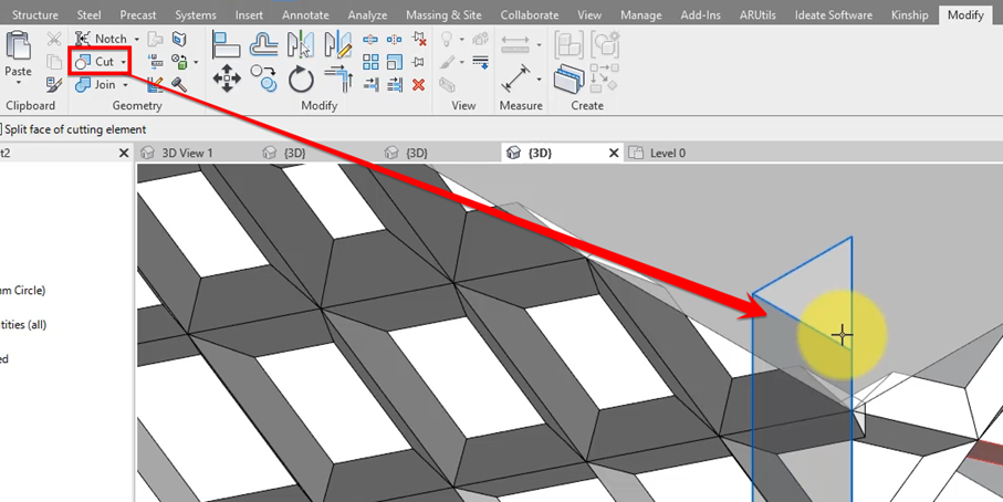
Use the Cut command and let this new solid be the cutting tool, you can then cut each panel on 1 side of the intersection back. This gives them the final geometry they should have. This trick is better showed than told, so refer to the video tutorial if you find this difficult.
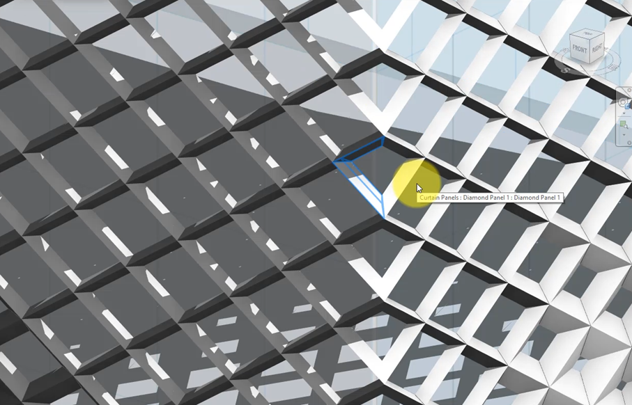
Repeat this trick with a second triangular extrusion on the opposite side. You can then cut panels on the opposite of this edge the same way using this new extrusion. The result will look like this:
You have now finished this tutorial. Congratulations! The result is of course a fully parametric façade system which you can further fine-tune and develop using the Dynamo script and the curtain wall panel family we built together.
I hope you enjoyed this tutorial. See you in our next one!
Subscribe to our channel here for more tutorials like this every day!


Hello, awesome video thank you. Only in the video you said you would post the Python Script for the Dynamo script in the comments below but I can’t see them anywhere on your site or youtube. Could you please share?
Thank you
Sorry for the delay! The script is here: https://rv-boost.com/wp-content/uploads/Dynamo-Facade-with-multiple-attractor-shapes.zip
I couldn’t run the file after i downloaded it
Hi,
Cannot seem to access the script file. It seems to have been corrupted.
Could you help?
Please make sure you open the script file in Dynamo version 2.0 or later. The file itself isn’t corrupt.
well link has still problem could you please share once again ?
Sure! Here it is: https://rv-boost.com/product/dynamo-script-create-adaptive-curtain-wall-with-multiple-attractors/
The video is very clear for me to follow. But I stuck at one problem when drawing an ellipse on reference plan where is filled (??). Please help to see where are goes wrong. Because of this problem, the dynamo is failed to convert the ellipse. Thank you very much.
When you start drawing the ellipse, make sure your Option Bar (usually below the Revit ribbon) is set to exactly the same state as in the video. The ellipse should then not fill itself after being drawn.
can you please post the text of pyhton script because i coulndt run it as well , thanks
what was the problem when you tried running it
Hello, I have a problem, and it is that in the revit drawing plane, I appreciate the points and ellipses of dynamo, how can I solve it? greetings and thanks, excellent your videos
Sounds like you need to set the workplane in Revit to one of the vertical faces of the mass before you can draw shapes on it.