Element Reference Point
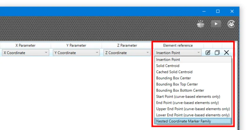
RV Live Coordinates allows you to specify exactly which point on an element it should report coordinates for. Below are all available options and their meaning:
Insertion Point
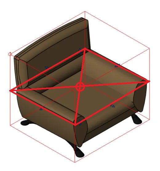
This option reports the coordinates of the point you clicked when placing a family instance in Revit. This works best for elements placed with a single click, such as trees or theatre seats.
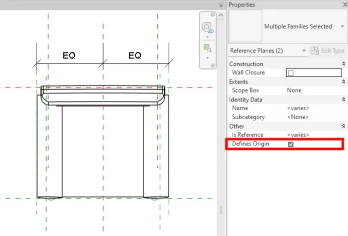
If you open the family, the insertion point is the intersection of the 2 reference planes with “Defines Origin” set to True:
Bounding Box Center
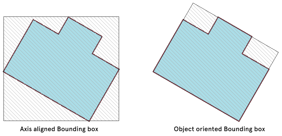
This option detects the bounding box of each element and reports the coordinates of the box’s center. The bounding box is a virtual box that is just big enough to fit all 2D and 3D geometries of the element inside it. The box’s center is simply the midpoint of a line connecting its min and max points.
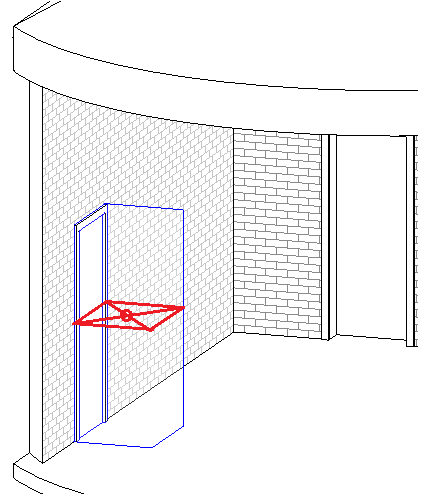
Note that this method can give unexpected results if the family has sizeable 2D geometries, such as a door with swing lines drawn in plan view:
Another caveat is Revit always orients bounding boxes to the global X, Y & Z axis. If your elements aren’t globally aligned, this method may not be suitable.
If you don’t want to include 2D geometries like detail lines and filled regions inside the family, use the Solid Centroid option below instead.
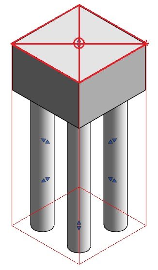
Bounding Box Top Center
For some categories like Structural Foundation, you may want to get the elevations/coordinates at the top of the elements. This option makes that task easy. It still detects the bounding box that encloses all 3D and 2D geometries. Next, it will compute the center point of the box’s top surface and report the coordinates of that point.
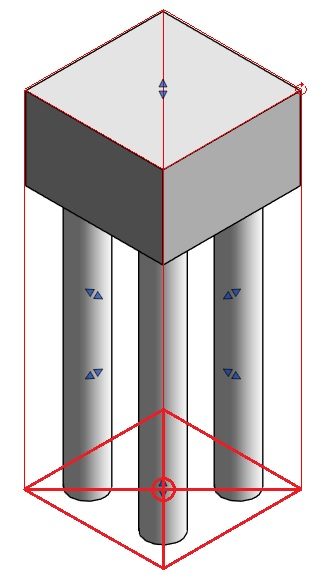
Bounding Box Bottom Center
On the contrary, bottom elevations/coordinates are more important for some other Revit categories. If that’s the case in your project, simply use this option to make the app detect the center of the bounding box’s bottom surface.
Solid Centroid
Some Revit families contain annotation lines and detail items, such as a dashed rectangle around a power generator showing a clearance/maintenance zone required for that equipment.
While important for other purposes, these annotation objects typically aren’t relevant to the actual geometry of the Revit object we want to report coordinates for. That’s when this option comes in handy.
If selected, this option instructs the app to:
- Extract all solids from the family instance
- Get the bounding box of each solid
- Compute a combined bounding box for all those individual boxes
- Report coordinates of the center of this combined bounding box
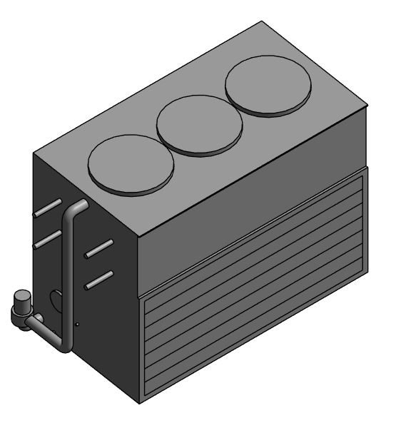
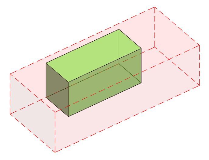
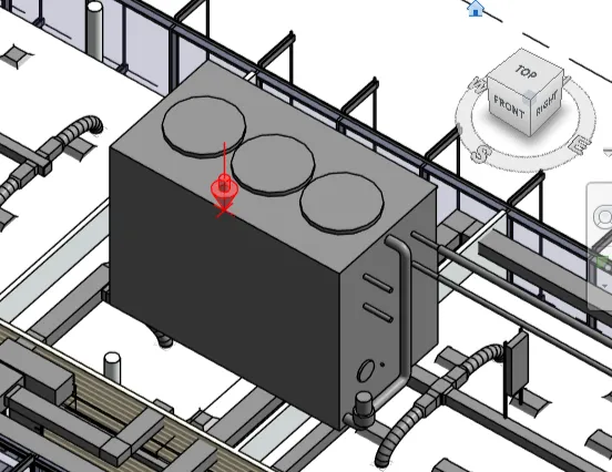
For example, the app will detect multiple bounding boxes for the cooling tower above:
- 1 biggest box for the main casing
- 1 box for each fan on top
- 1 box for each pipe and pipe fitting/accessory on the left of the main tower housing
The app will then combine all these bounding boxes and read that box’s center point as the coordinates of the cooling tower.
Cached Solid Centroid
This option works on the same principle of “Solid Centroid” but it also caches the solid extraction result by Revit family type. This is because extracting solids from Revit objects is computationally heavy and can be slow in large models.
This option is most suitable if the instances of your Revit family type are geometrically identical. For example, all doors of the same type so have the same dimensions. It can however produce incorrect coordinates for objects whose geometry can vary at the instance level. For example, wall openings with flexible widths, furniture items with flexible lengths, or adaptive objects like pipe/duct fittings.
If selected, this option will extract solids from only the first instance of each family type. Other instances of that type will be assumed to have the same geometry. The app then proceeds to compute the combined bounding box of each element’s geometry and then report the coordinates of that bounding box’s center.
Start Point & End Point
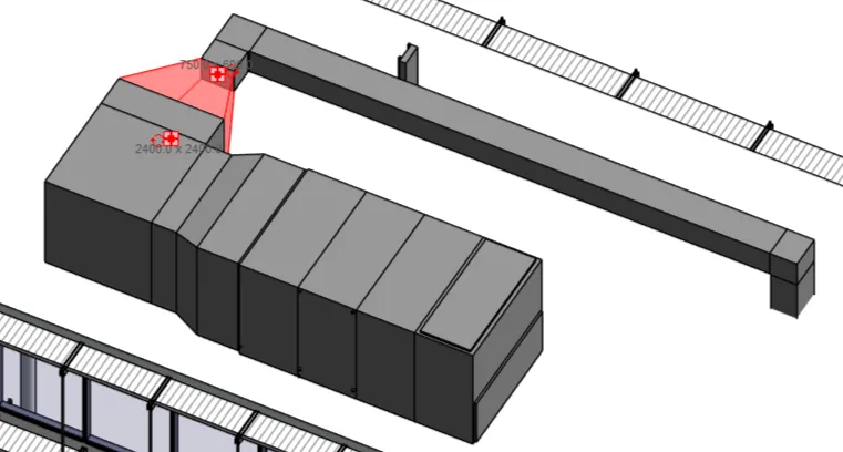
For line-based or curve-based Revit elements such as structural beams or walls, it’s often necessary to report the coordinates of their start and end points. In RV Live Coordinates, you can do this using 2 configurations like this:

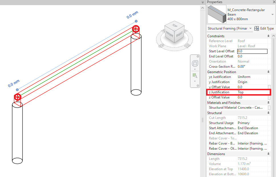
For structural beams, note that the “z Justification” property will determine their start and end points. The below beam uses top justification and the image shows where RV Live Coordinates reads its endpoints.
On big projects, it can however be tricky to remember in which direction you drew a line-based element! If you can’t recall, the “Upper/Lower” end points method below can be useful.
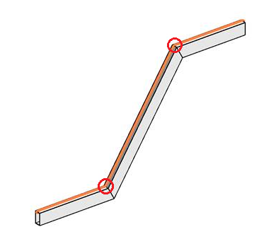
Upper End Point & Lower End Point
This method is particularly useful for sloping line-based elements such as structural beams of stairs or ramps. RV Live Coordinates will compare the heights of the element’s endpoints to determine its higher and lower ends regardless of the direction in which it was drawn.
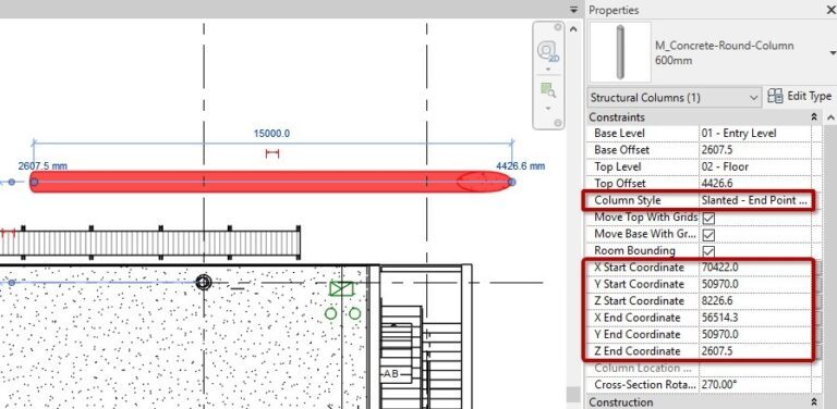
This also works well with slanted columns or any other line/curved-based Revit objects.
Nested Coordinate Marker Family
What if all the element reference methods so far don’t meet your needs? Not to worry! RV Live Coordinates also allows you to specify which point on the element to report coordinates from. You will be able to do this in the family editor, so it’s only semi-manual.
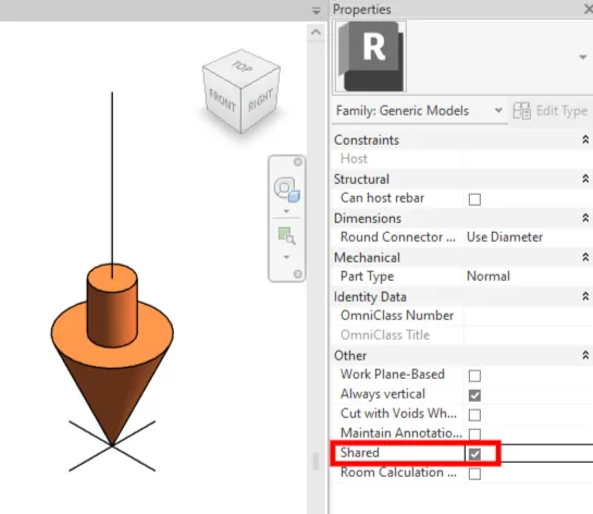
To begin, create a point-based Revit family to use as the marker. We will soon load this marker into the family you want to report coordinates for, and then reload that family into the project. In the project, we must be able to select the marker without selecting its host. This usually means the marker family needs to have Shared set the True:
Don’t have a marker yet? You can download our family like this. Just remember to make it “Shared” as shown above.
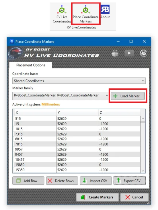
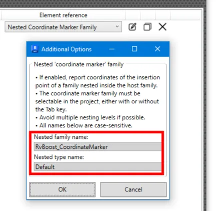
Back to the project, run RV Live Coordinates. Next, select “Nested Coordinate Marker Family” from the menu and a window will pop up, asking you for the family name and type name of the marker. If you don’t see this window, click the small “pen” button next to the dropdown menu to access the same options.
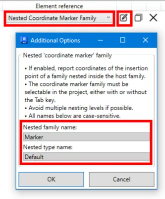
Fill in the family name and type name of the marker family you want to use, and then click OK.
And that’s it! Next time you update coordinates with the app, it will check each object of the specified category, find the marker inside each one, and report the coordinates of the marker’s insertion point.
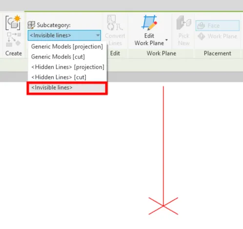
Of course, you probably don’t want the marker always visible in the model. An easy way to hide it is by having it comprised of only invisible lines:
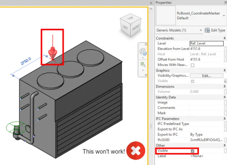
RV Live Coordinates will still see the invisible lines in the model and report coordinates correctly. However, it won’t work if you hide the marker by setting this property in the host family:
One final thing to note: the marker family should be placed directly inside the host family. This means avoiding situations where we have the main family A containing nested family B, which in turn contains nested family C, and then we place the coordinate marker inside family C. Try to place the marker in the top-level family A if possible. Nesting the marker deeper should still work but might be more unstable.
Is there anything unclear? Let us know at support@rv-boost.com!