Quick Start
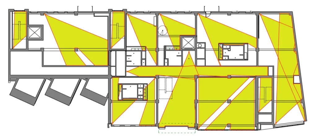
RV CameraPlanner makes it easy to generate filled regions that visualize your CCTV camera’s field of view inside the building. For example, we have cameras colored in orange in the ceiling plan below:

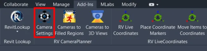
Before creating the first filled region, we need to configure how the app should calculate the field of view. Click “Camera Settings” under Revit’s Add-ins tab to begin:
Since this is the first time we open this window, it automatically created for us a default configuration card:

When you select a card on the left, the panel on the right shows all settings associated with that card. The camera category is set as “Security Devices” by default, but you can change it if your Revit cameras are of a different category:

Next, we need to select a Filled Region type the app should use when generating the field of view:

For viewing distance and vision angle of each camera, you can specify those directly for all cameras of the selected category, like this:
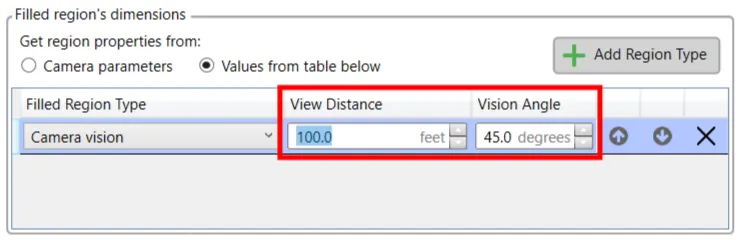
If the viewing distance and vision angle are different for each camera, you can specify these in 2 custom camera parameters instead, and then select the parameters here:

When ready, click OK to save your settings. Next, click the “Cameras to Filled Regions” button and then select the CCTV cameras you want to process:

And that’s it! After a few seconds, the app will generate filled regions for all your selected cameras. Each region shows exactly the plan area covered by each camera’s vision angle and viewing distance:
If the result doesn’t look exactly as you expected, don’t worry! There are manymore settings we can tweak to make RV CameraPlanner produce the required output. The next few articles below will show all you need to know.